Showing posts with label WOOD. Show all posts

Router table with power lift, built around Ikea BEKVÄM and parts from old drafting machine

This is my (quite) completed router table built around IKEA kitchen cart BEKVÄM and a precise drafting machine cannibalized.


Router is a Bosch POF 1200.
Router table is equipped with power lift feature (missing only router support in the photos).

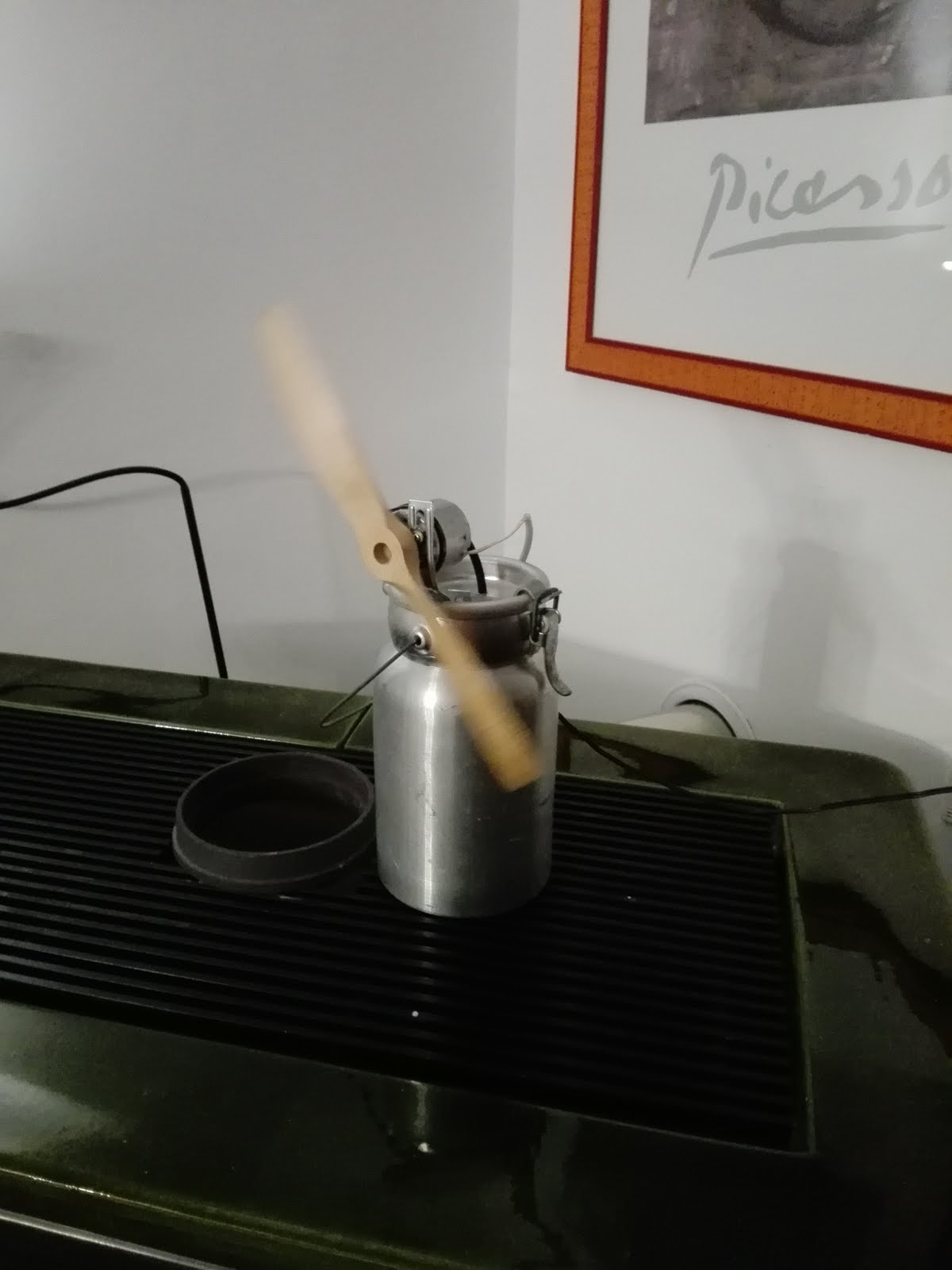
DIY: Stove fan

Our living room is equipped with an old wood stove.
The stove is placed in a corner and the room is very long.

Sitting in the middle of the room, i cannot feel the warm. This because the heat goes straight up to ceiling, and only a fraction of heat (radiant) directly arrives to the body.
After a couple of hours the room is quite warm but remains a gradient in the room based on the distance, so too hot near the stove, too cold far away from it.

Another problem is that i have to leave a cup of water on the stove to keep the air humidified.

On the web you can find quite a lot of heat powered stove fan, based on thermoelectric effect (peltier) or based on simple heat engine (stirling).
The price is between 50 and 150 bucks, and none of these provides humidity correction.

My solution is reasonably priced (zero, using items found in garage), and guarantees horizontal air movement and air humidification at the same time. The only drawback is that is powered by a small phone charger and is not heat powered.


Items to build it
  • A metal milk container from Alps pastures (a similar item will work: has to contain liquid, be sealed and withstand high temperatures);
  • A small DC motor;
  • A wood blade for rc airplane;
  • A phone charger;
  • A piece of black rubber tube;
  • A bracket for the motor;
Pay attention to isolate motor from the bracket using rubber, and also isolate the electrical connection with silicone tube.

Humidification
The milk container is filled with water. After half an hour the water starts to boil and a small tube (the only orifice) direct steam to the wood blades.

Energy usage
Considering a price of 0.30 euro/kWh and a consumption of 3.6W (6V, 600mA), a mid price for the stove of 100 bucks, i need to switch on the fan for 92000 hours (380 years considering the occasional stove usage) to match the initial cost of the stove (ok, i'm not considering inflation, but this makes the idea).

COIN-OP: mini arcade cabinet photos

The completed COIN OP ARCADE machine (with missing only coins drawer)


The interior (with back cover removed):
In the upper part is located the usb pc speakers.
In the bottom side is visible the temporary ... coin storage solution.

Don't miss the Arduino uno keyboard previous series of posts.

Update 2016/11/23: check out sheet metal plate upgrade and coin drawer window on this post

COIN-OP: mini arcade cabinet build log 3/3

This is a 3 part post, in which i cover:

INTRODUCTION Arduino Uno Keyboard emulator - dfu mode / programming
SKETCH Arduino Uno keyboard emulator - ino sketch
COINS Coin acceptor (3 coins)

Source code is available on Google Drive folder:
SOURCE CODE

COIN ACCEPTOR
I use this model by SparkFun: CH-923 sourced at Robot Italy.
The device is a robust independent coin acceptor with more than 95% coin recognition performance.
Here after the manual:

Is possible to use 1, 2 or 3 coin types. Each time an unrecognised coin is inserted the acceptor ejects it in the front.
If recognised, the coin drop from the bottom.


Voltage is +12Vdc sourced from the PC ATX connector (Yellow for 12V, Black for GND). Output is TTL compatible so you can use directly with arduino. You need only to interconnect GND from PC to GND to the Arduino part.

The output is programmable, so each time you insert a coin you can choose how many pulses the Acceptor are sent to the Arduino.

Because i use Euros coins, i've set 10 cents / pulse:
20 euro cents: 2 pulses
50 euro cents: 5 pulses
1 euro: 10 pulses
You can use a metal coin of your choice, and once programmed it will works with your coins.

On the Arduino Uno part i've connected the Grey wire to Pin 2 (INTERRUPT 1) acting as a switch using a 10k pulldown resistor. Each time a pulse is received an internal counter is incremented by 0.10 euro.
In the main loop each time the counter is > than 20 cents, is decremented by 20 cents and a keystroke is sent to PC.
The corresponding keystroke is then mapped on Mame as coin insert.

The sketch part is really simple:

  • Declare coinvalue variable as volatile so you can change in interrupt routine
  • Attach in Setup the interrupt handler using: attachInterrupt(digitalPinToInterrupt(PIN_COIN), coinInserted, FALLING);
  • Handle the interrupt incrementing the coinvalue variable, and setting coinchange bool to 1.
  • In the loop - once the coinchange value is set to 1 - decrement the coinvalue variable and send the keystroke as described in the previous post. Because the Byte is shared with Start and Menu routine, immediately send the keystroke to clear the byte usage for the latest Start/Menu routine.

The coin acceptor up to now was really reliable, so the arduino keyboard.
Customize it as you need.


COIN-OP: mini arcade cabinet build log 2/3

This is a 3 part post, in which i cover:

INTRODUCTION Arduino Uno Keyboard emulator - dfu mode / programming
SKETCH Arduino Uno keyboard emulator - ino sketch
COINS Coin acceptor (3 coins)

In this post is covered for convenience the Arduino sketch part.

The sketch uses a simple Serial.write(buf) to send a keystroke / keyrelease for each switch, like
Serial.write(buf, 8); // Send keypress

The HID message sent in the serial part is a byte array:
uint8_t buf[8] = { 0 };

Byte 0 is a modifier bye. If you set a bit with another keypress, you will have a combination like CTRL-X.

Modifier keys:
Bit 0 - Left CTRL
Bit 1 - Left SHIFT
Bit 2 - Left ALT
Bit 3 - Left GUI
Bit 4 - Right CTRL
Bit 5 - Right SHIFT
Bit 6 - Right ALT
Bit 7 - Right GUI

Byte 1 - Not used

The useful part starts from byte 2 up to byte 7, where are mapped the HID active key usage codes. This accepts up to 6 keys being pressed at the same time.

Because i have more than 6 keys, i had to join more than one key in each byte. In this situation the same byte is used to send KEY_UP or KEY_DOWN: this works because the switches are inside a joystick and cannot be sent at the same time.

This is my mapping, modify as you require your situation (S1 means Switch 1):
#define PIN_UP 6
#define PIN_DOWN 4 
...
My joins are:
Byte 2: PIN_UP & PIN_DOWN
Byte 3: PIN_LEFT & PIN_RIGHT
Byte 4: PIN_S1 & PIN_S5
etc...
Byte 7: PIN_START & PIN_ESC & PIN_COIN

This mapping helps to send joystick on upper left (PIN_UP + PIN_LEFT) while pressing a fire switch (PIN_S1) and jump switch . Less attention needs the Start/Select and Exit switch.

Each time the loop function finds a specific pin press, in the buffer is wrote the key code. 
To send the keypress "Enter" write 0x28 into the buf, using this code:
buf[2] = 0x28; //Or define a variable for convenience

To emulate a key release: buf[2] = 0;

More HID Keyboard codes could be found at this link

Debounce: I carefully tested the sketch on debounce matter. With simple timing check, a debounce routine is not needed at all.

In the next part i'll cover the coin acceptor part.

COIN-OP: mini arcade cabinet build log 1/3

This is a 3 part post, in which i cover:
  1. INTRODUCTION Arduino Uno Keyboard emulator - dfu mode / programming
  2. SKETCH Arduino Uno keyboard emulator - ino sketch
  3. COINS Coin acceptor (3 coins)
Source code is available on Google Drive folder:
SOURCE CODE

INTRODUCTION


Finally i had the opportunity to complete the Arduino Uno Keyboard emulator, including the Coin Acceptor (3 coins) from Sparkfun (SPARKFUN COM-11719).

After some tweaking the emulator works like a charm.
I had some trouble with key press & release, because we need to leave to OS the key repeat function.
The current version works very well with Mame on Windows 98.

The Keyboard HID hex is based on LUFA and is needed to make Arduino Uno act as a Keyboard, Joystick, Mouse, etc: for more information, check this link Arduino UNO Keyboard HID version 0.3 from darran

There is a copy attached also to this post. Please use at your own risk, this is working for me, but i cannot guarantee for your hardware.


A note: while using keyboard LUFA hex, pins 0 and 1 (TX and RX) will not work as digital pin, so don't use them.


  • From terminal, change directory to the sketch dir, and execute:
    • sudo dfu-programmer atmega16u2 erase
    • sudo dfu-programmer atmega16u2 flash --debug 1 Arduino-keyboard-0.3.hex
    • sudo dfu-programmer atmega16u2 reset
  • Disconnect and reconnect usb
If you want to revert Arduino to usb bootloader to update the sketch (this is the tricky part), simply repeat these steps:
  • Disconnect and reconnect usb
  • From terminal, change directory to sketch dir, and execute:
    • sudo dfu-programmer atmega16u2 erase
    • sudo dfu-programmer atmega16u2 flash --debug 1 Arduino-usbserial-atmega16u2-Uno-Rev3.hex
    • sudo dfu-programmer atmega16u2 reset
  • Disconnect and reconnect usb
The dfu mode is always available, i never had trouble with this.

In the next post, i'll cover the keyboard sketch to make the Arduino working.

COIN-OP: mini arcade cabinet build log

My father bought some wood panels from Ikea. He donated two to build a mini arcade cabinet for my son. The arcade cabinet will use a raspberry pi with PiMame and some Sparkfun arcade goods, like a Zippy arcade joystick and concave buttons. In this post you'll find a short build log. The cabinet is 1 meter tall (39") and 0.42 meter wide (17").

Cutting the hpl boards. Masking tape installed for marking


The monitor, a 19" sony sdm-hs95

Build log:


Monitor installation test


PEATOL/TAIG: the most beautiful affordable metal lathe


I bought a PEATOL/TAIG because i need a small lathe (despite i have a 7x20 lathe) i can operate in my house. I have known about it from the conspicuous fans all over the world.


Peatol/Taig lathe overview

The Peatol 0,18kW motor, 1360 rpm

Here some links if you want to know more about PEATOL/TAIG:
Peatol Machine Tools: the home of PEATOL/LATHE;
Deansphotografica: beautiful projects;
CarterTools: the biggest resource i know about taig;
LeeValley Instruction booklet;

I received it from Peter of Peatol (UK) on August, and now i'm showing it once assembled the base, the motor and it's fully functional. The motor was blue so i repainted to black.

I assembled also the motor mount from aluminium with primitives dovetails. My version of lathe come with powerfeed already installed and a sturdy block of aluminium for raise the entire lathe.

This is my start package:

1015Micro lathe with power feed
1030Four jaw chuck, with reversible, heat-treated steel jaws
10921/16"-3/8" Jacobs chuck
1150Drilling tailstock - lever operated
1151Needle bearing centre - spring loaded
1160Spare belt
11616 step pulley set (2 pulleys) including Vee belt for 11mm motor shaft
10956 piece tool bit set - HSS, left & right, round nose, boring bar, cutoff, 45 degree chamfer
1200Compound top slide - mounts on cross-slide for cutting angles and tapers - with toolpost
1002New electric motor - 11mm shaft
 ?Drill chuck arbour - attaches Jacobs chucks to headstock spindle
1173T-bar cutoff tool, height adjustable


Peter form Peatol said me this is a very comprehensive set of components to give a working lathe, and i must admit he was right.
For the base i used a wood block from a ikea countertop (very hard), a drip pan upside down and a wooden frame to finish the base. To lock the lathe and the motor's dovetail to the wood base i used brass barrels in the bottom plane.


A review: this lathe is beautiful, sturdy, small, precise, simple to assemble and use. A must for every workshop. This is only a start because there are a lot of implementations you can do to this little lathe.


The pulley system, note the rubber band
The toolpost, simple and effective
To enable the power feed you simply lock the handywheel 
I think i will replace the spring with a coupler 
The Taig headstock


My home made motor mount with dovetails

The depth stop

I bought also two IGaging Scales (IGaging site), a 6" and a 12" which i've cut to size and mounted on X and Y axes. I've planned to convert the DRO to Yuriy's Touch Dro (Yuriy's Toys Dro) using a tablet and a TI launchpad.


A closeup of the lathe and IGaging Scale 
The IGaging side support
The other IGaging support
The stock IGaging magnetic reader.
With IGaging in this position you lose some x width with tool post installed.


Update 2016/11: check out also Peatol/Taig steady rest , radius turner , milling attachment on this blog.

CNC EMBROIDERY: la base in legno, parte III

Preparativi per il matrimonio.

Il tensionatore della cinghia, semplice ed efficace. Richiede tuttavia la pista libera.

Dopo qualche aggiustamento le cinghie non slittano. Ruotando a mano l'albero lo spostamento dell'asse Y non offre particolare resistenza.

La regolazione del porta cinghia forse non serviva.

Ho dovuto sostituire la boccola con una boccola compensata perché l'allineamento non è perfetto

CNC EMBROIDERY: la base in legno, parte II

Ecco qualche progresso della costruzione.
La base della macchina è realizzata come uno sportello, ovvero con telaio.
Lo stesso telaio, gli incastri, le mortase ed i tenoni sono stati fatti con la piccola MF70, spostando i profilati nella morsa. Il risultato è buono, se non fosse per il fatto che ho previsto poco gioco tra i pezzi per cui l'insieme finale non si chiude al 100%. Il prossimo verrà sicuramente meglio.

Tutti i pezzi tagliati:

Particolare della mortasa e tenone d'angolo:


Il telaio montato: 

Assemblato. Notate gli spazi nel telaio, i pezzi centrali erano indubbiamente troppo lunghi di 1 o 2 mm:


Popular posts