Once assembled and tested, i had a lot of data collected from brushless spindle controller, i've used to implements a better control method, a PID control. I've spent long time updating the code to find what was going wrong. Regarding PID, there are a lot of good articles in the web, some implemented also on the Arduino universe. Start your readings from the incredible series of post from Brett, if you want to know more about PID.
In this post i want to describe my solution to some of the headache i had to implement:
- Keep it fast if what you want to control react fast (a spindle is really different from sous-vide or temperature PID room controller). My timing between refresh is now 50ms.
- Keep it steady, eliminating every distraction from the PID computation (like delays).
- Linearize the output of the PID, before applying to the ESC to get rid of the PID constants.
- Try to guess the output value, before enabling PID.
- Divide the PID constants in aggressive and conservative variants depending from the error between desired set point and actual reading.
- Don't try to find a magic method to find constants. Try various values starting only from progressive, then enabling integrative, and only at last using derivative.
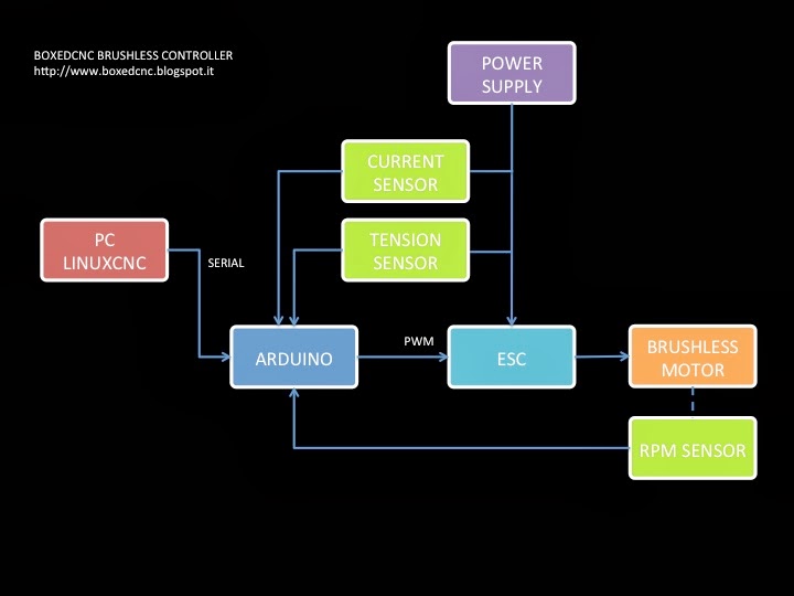
The next image shows the schematic of the brushless controller. There are four sensors in the system, but the fourth is not showed because is a temperature sensor.
The main loop in CNC mode use the GCode Spindle commands (like S5000) as target value to control with PID in a closed loop the motor RPM, trying to minimize the error between target and actual speed.

The major drawback i discovered using the affordable Turnigy ESC is the non linear response of the motor's rpm in the basic free spinning condition (without torque applied). As you can see in the next image, the RPM relation between Arduino PWM uS interval and motor RPM is something similar to a quartic function. I think this is quite common when using the writeMicroseconds function approach. In fact you can control the servo with high precision writing an interval typically between 1000uS and 2000uS. In the next graph is possible to see the real data registered regarding RPM and the Power Source output tension and current given to the ESC. Without any resistance applied to the motor's shaft, the ESC absorbs circa 70W at the maximum speed. The power source drop voltage between zero and maximum speed is only 0.30V (from 12.87V to 12.50V).

To avoid strange PID behaviors, i needed to implement a fast transformation function.
The rest of the post is about how i've implemented a SMA (Simple Moving Average) to smooth the RPM readings, and about the linearization of the output of the ESC.
The start is a simple moving average using integer array to take care of the fast RPM refresh process, without dedicated onboard hardware. This was software implemented using a simple array which hold a certain number of integer numbers (from 30 to 50). These values are the microseconds between two consequents falling edge (or raising, is the same) of the rpm optical sensor, collected on interrupt pin. This happen continuously with a period in a range from 2.000 and 15.000 uS. The array index is incremented every interrupt, and is zeroed using the modulo operator in one code row.
The result is a Simple Moving Average of the continuous RPM data, which is implemented using this code in the interrupt function:
void rpmMeter() //INTERRUPT CALLED FUNCTION{RPMIndex = (RPMIndex +1)%(RPMIndexSize-1);RPMTimes[RPMIndex] = micros() - RPMTimeold;RPMTimeold = micros();};
Once 50ms i compute the sum of the array, and divide the result by number of elements in the array to obtain a smoothed RPM fresh value.
The next step is to transform the output from the horrible quartic function to a simple linear response.
This happens using another array containing the uS timing values at which corresponds the desired output. I think this is a fast method because the loop only need to lookup in a prewritten array using the index as input.

The next graph shows the test results without smoothing (real data). In the x axis there are the values of the linearized output range, in the y axis the RPM logged.


