Showing posts with label ARDUINO. Show all posts

IOT RECIPE 03: Pellet / Wood chips level sensors

In this post i'll cover actual sensor setup for pellet and wood chips bulk level monitoring.

Pellet bulk level sensors

How to monitor pellet bulk level if you can't access to warehouse?
My warehouse is a room covered by wood, with sloped floor and a moving reclaimer on the center. The total volume is approximately 12 cubic meters and once filled i've no access to the room.


Obviously i need to know residual pellet level, so a pellet bulk sensor is needed. While googling i've found few examples, all of them related to water level in tank and using ultrasonic distance sensor approach.

The room is more or less 2 by 3 meters: in this configuration, pellet or wood chips forms non uniform piles in the room, with lower point just above the reclaimer area, so is needed to use an array of sensors averaged to find the level: 9 ultrasonic sensors are arranged in a matrix configuration.

Ultrasonic sensors

For the project i've selected HC-SR04: the sensor is a low cost complete ultrasonic measurement device. The sensors are housed in waterproof electrical box.

Once activated a signal burst is emitted from the emitter, then the signal is captured from the receiver, mirrored by a surface. Using simple timing formula based on sound speed, the library output distance in cm. Simple. 3 cm to 2 meters is the real distance range, while effective usage suggests the sensor is not so accurate over time: in my experience temperature compensation is needed to give at least not wrong measurements (15% of fluctuation is possible).

Most libraries provides averaging for each reading, with 10 to 25 signal bursts before measurement average.

From distance to weight

Pellet weight in bulk storage is more or less 650 kg/mc.
To provide weight measurement the equation is simple:

Estimated weight = Average(empty distance - measured distance)*(area)*(bulk weight)


Data acquisition

To acquire 9 sensors outside warehouse a lot of cables are routed outside warehouse to an external waterproof electrical box.

The little circular window in the front of electrical box is PMMA window sealed with hot glue (my new electronic projects best friend). 

In the box i've installed an Arduino Mega with three additional sensors:
  • A remote DHT22 inside pellet warehouse to provide internal reading of temperature and humidity;
  • DHT22 to provide same readings of external conditions;
  • A three-in one sensor: light, pressure/altitude and temperature

Measurement routing

Distance between Arduino Mega and Raspberry PI is more or less 4 meters. After a bit of googling, i've found a 5 meters USB cable is reliable. I can confirm is true.
The USB cable connect Arduino to RPi inside the boiler room (gray cable coming from the top of the electrical box).


Inside the box a Raspberry PI with Node-Red with MQTT client (more details in the future).
Another Arduino is installed and connected to read out energy monitor.
RPi communicates with a central server (another RPi) using ethernet.


RC SERVO ROBOT ARM: Weekend project

This is our weekend project: a simple RC servo robot arm. 


Host controller is Mac using Python scripting, while servo controller is a spare Fubarino SD.


I tried with MSP430 Launchpad, but Serial + 3 servos was over the capability of this little Mac-hated board. Fubarino is a cherry plenty of power, and the ported SoftwareServo library from ChipKit is stable and effective.
Fubarino accepts directly joint angle in ms. Python script uses a simple Inverse Kinematics (Updated versione: math credits to COŞKUN YETİM):

def ik(self, position):
#ARM LENGHTS
l1 = self.arm1
l2 = self.arm2

#END EFFECTOR POSITION IN RESPECT OF ORIGIN NODE
x = position.x - self.home_position.x
y = position.y - self.home_position.y

#TO LIMIT END POSITION WITHIN ARM REACHABLE CIRCLE
dist = min(l1+l2, sqrt(x*x + y*y))
dub = sqrt(x*x + y*y) / dist
x /= dub
y /= dub

#SIMPLE, NO?
thetar = acos(x/dist)
theta1 = acos((l1*l1 + x*x + y*y - l2*l2) / (2*l1*dist)) + thetar
theta2 = pi - acos((l1*l1 + l2*l2 - (x*x + y*y))/(2*l1*l2))

self.set(180-degrees(theta1), 180-degrees(theta2))

Graphic is provided by a simple Svg to path script. The library used (svg.path) can provide point coordinates for Line, Arc, CubicBezier and QuadraticBezier without pain. All graphic may be created within Inkscape.


Overall code may be downloaded at this link.

IOT RECIPE: 02 Energy Monitor

In this post i'll cover actual sensor setup for energy monitor.

Energy monitor

To evaluate power consumption i've routed main cable coming from utility energy monitor in a new electrical panel. In this panel i've installed:
  • 3 three-phase energy meter (16 kW of maximum power)
  • 1 single-phase energy meter
This is an internal view of my setup inside an ABB electrical panel (upper part, with two of these energy monitor) after thermal-magnetic circuit breaker and surge protector.

For this duty i preferred to go with an industrial solution, because i was not confident with DIY solutions on main power side.
My solution is a products from Italian manufacturer LOVATO:
LOVATO DMED300T2 is a compact (four modules) energy meter. The main advantage is the presence of two programmable pulse output (up to 1000 pulses/1kWh or programmable threshold).
The output is an open collector, in which each pulse has a duration of 60ms: an open collector is a transistor based output that can be read by an external PLC (like arduino).

The electrical connection requires only to route an input pin of the arduino to open collector and connect the two IC grounds to have the same reference level and let current from arduino to flow once open collector is open.

There are two methods to read these output, with interrupts or with pooling.
Because i had only one external interrupt, i had to go with pooling: loop forever and check if digital input is high or low. If is high, and previous one was low, than increment a counter and go on to next input. 

First of all, in my system maximum power is 16 kW: this means each hour i can have a maximum number of pulses of 16 * 1000 = 16.000 pulses/hour equal to 4.45 pulses/second, each one of 60 ms.
If entire loop timing is less than 60ms, no pulse is missed.

Because open collector is transistor based, i found no debounce routine is needed (situation like button press may need a stabilisation in input reading).

My piece of code for pooling is:

//INPUT SETUP
pinMode(LOVATO1, INPUT);           // set pin to input

digitalWrite(LOVATO1, HIGH);       // turn on pullup resistors

//INPUT LOOP
READ1 = digitalRead(LOVATO1);

if (READ1 != LASTSTATE1) {
    if (LASTSTATE1 == 1) {
      COUNTER1 ++;
    }
    LASTSTATE1 = READ1;
  }

Taking into account the time delta between reading A and reading B (60s in my case), is possible to average the energy consumption during this period, and to define average power consumption during the period.
Passing via serial milliseconds and pulse numbers between loops, i can reduce the time spent communicating with host, leaving calculation on other side.

Resulting chart of 1 day power consumption average (1 tick/30 minutes):


COIN-OP: mini arcade cabinet build log 3/3

This is a 3 part post, in which i cover:

INTRODUCTION Arduino Uno Keyboard emulator - dfu mode / programming
SKETCH Arduino Uno keyboard emulator - ino sketch
COINS Coin acceptor (3 coins)

Source code is available on Google Drive folder:
SOURCE CODE

COIN ACCEPTOR
I use this model by SparkFun: CH-923 sourced at Robot Italy.
The device is a robust independent coin acceptor with more than 95% coin recognition performance.
Here after the manual:

Is possible to use 1, 2 or 3 coin types. Each time an unrecognised coin is inserted the acceptor ejects it in the front.
If recognised, the coin drop from the bottom.


Voltage is +12Vdc sourced from the PC ATX connector (Yellow for 12V, Black for GND). Output is TTL compatible so you can use directly with arduino. You need only to interconnect GND from PC to GND to the Arduino part.

The output is programmable, so each time you insert a coin you can choose how many pulses the Acceptor are sent to the Arduino.

Because i use Euros coins, i've set 10 cents / pulse:
20 euro cents: 2 pulses
50 euro cents: 5 pulses
1 euro: 10 pulses
You can use a metal coin of your choice, and once programmed it will works with your coins.

On the Arduino Uno part i've connected the Grey wire to Pin 2 (INTERRUPT 1) acting as a switch using a 10k pulldown resistor. Each time a pulse is received an internal counter is incremented by 0.10 euro.
In the main loop each time the counter is > than 20 cents, is decremented by 20 cents and a keystroke is sent to PC.
The corresponding keystroke is then mapped on Mame as coin insert.

The sketch part is really simple:

  • Declare coinvalue variable as volatile so you can change in interrupt routine
  • Attach in Setup the interrupt handler using: attachInterrupt(digitalPinToInterrupt(PIN_COIN), coinInserted, FALLING);
  • Handle the interrupt incrementing the coinvalue variable, and setting coinchange bool to 1.
  • In the loop - once the coinchange value is set to 1 - decrement the coinvalue variable and send the keystroke as described in the previous post. Because the Byte is shared with Start and Menu routine, immediately send the keystroke to clear the byte usage for the latest Start/Menu routine.

The coin acceptor up to now was really reliable, so the arduino keyboard.
Customize it as you need.


COIN-OP: mini arcade cabinet build log 2/3

This is a 3 part post, in which i cover:

INTRODUCTION Arduino Uno Keyboard emulator - dfu mode / programming
SKETCH Arduino Uno keyboard emulator - ino sketch
COINS Coin acceptor (3 coins)

In this post is covered for convenience the Arduino sketch part.

The sketch uses a simple Serial.write(buf) to send a keystroke / keyrelease for each switch, like
Serial.write(buf, 8); // Send keypress

The HID message sent in the serial part is a byte array:
uint8_t buf[8] = { 0 };

Byte 0 is a modifier bye. If you set a bit with another keypress, you will have a combination like CTRL-X.

Modifier keys:
Bit 0 - Left CTRL
Bit 1 - Left SHIFT
Bit 2 - Left ALT
Bit 3 - Left GUI
Bit 4 - Right CTRL
Bit 5 - Right SHIFT
Bit 6 - Right ALT
Bit 7 - Right GUI

Byte 1 - Not used

The useful part starts from byte 2 up to byte 7, where are mapped the HID active key usage codes. This accepts up to 6 keys being pressed at the same time.

Because i have more than 6 keys, i had to join more than one key in each byte. In this situation the same byte is used to send KEY_UP or KEY_DOWN: this works because the switches are inside a joystick and cannot be sent at the same time.

This is my mapping, modify as you require your situation (S1 means Switch 1):
#define PIN_UP 6
#define PIN_DOWN 4 
...
My joins are:
Byte 2: PIN_UP & PIN_DOWN
Byte 3: PIN_LEFT & PIN_RIGHT
Byte 4: PIN_S1 & PIN_S5
etc...
Byte 7: PIN_START & PIN_ESC & PIN_COIN

This mapping helps to send joystick on upper left (PIN_UP + PIN_LEFT) while pressing a fire switch (PIN_S1) and jump switch . Less attention needs the Start/Select and Exit switch.

Each time the loop function finds a specific pin press, in the buffer is wrote the key code. 
To send the keypress "Enter" write 0x28 into the buf, using this code:
buf[2] = 0x28; //Or define a variable for convenience

To emulate a key release: buf[2] = 0;

More HID Keyboard codes could be found at this link

Debounce: I carefully tested the sketch on debounce matter. With simple timing check, a debounce routine is not needed at all.

In the next part i'll cover the coin acceptor part.

COIN-OP: mini arcade cabinet build log 1/3

This is a 3 part post, in which i cover:
  1. INTRODUCTION Arduino Uno Keyboard emulator - dfu mode / programming
  2. SKETCH Arduino Uno keyboard emulator - ino sketch
  3. COINS Coin acceptor (3 coins)
Source code is available on Google Drive folder:
SOURCE CODE

INTRODUCTION


Finally i had the opportunity to complete the Arduino Uno Keyboard emulator, including the Coin Acceptor (3 coins) from Sparkfun (SPARKFUN COM-11719).

After some tweaking the emulator works like a charm.
I had some trouble with key press & release, because we need to leave to OS the key repeat function.
The current version works very well with Mame on Windows 98.

The Keyboard HID hex is based on LUFA and is needed to make Arduino Uno act as a Keyboard, Joystick, Mouse, etc: for more information, check this link Arduino UNO Keyboard HID version 0.3 from darran

There is a copy attached also to this post. Please use at your own risk, this is working for me, but i cannot guarantee for your hardware.


A note: while using keyboard LUFA hex, pins 0 and 1 (TX and RX) will not work as digital pin, so don't use them.


  • From terminal, change directory to the sketch dir, and execute:
    • sudo dfu-programmer atmega16u2 erase
    • sudo dfu-programmer atmega16u2 flash --debug 1 Arduino-keyboard-0.3.hex
    • sudo dfu-programmer atmega16u2 reset
  • Disconnect and reconnect usb
If you want to revert Arduino to usb bootloader to update the sketch (this is the tricky part), simply repeat these steps:
  • Disconnect and reconnect usb
  • From terminal, change directory to sketch dir, and execute:
    • sudo dfu-programmer atmega16u2 erase
    • sudo dfu-programmer atmega16u2 flash --debug 1 Arduino-usbserial-atmega16u2-Uno-Rev3.hex
    • sudo dfu-programmer atmega16u2 reset
  • Disconnect and reconnect usb
The dfu mode is always available, i never had trouble with this.

In the next post, i'll cover the keyboard sketch to make the Arduino working.

EMBROIDERY CNC: Software completed

Feb, 2018 UPDATE: check the final machine result: 
EMBROIDERY CNC: first completed work

The software for the cnc embroidery is finally completed and fully functional.


Screenshot: Main screen

Screenshot: Palette selection

Screenshot: Color selection

Screenshot: Artwork translate panel

Screenshot: Grbl dashboard panel (realtime via browser thanks to Websocket)

Screenshot: G-Code Inspection panel


BOXEDCNC: Brushless ESC pwm response, linearizing output for PID control, and smoothing the sensor values

Once assembled and tested, i had a lot of data collected from brushless spindle controller, i've used to implements a better control method, a PID control. I've spent long time updating the code to find what was going wrong. Regarding PID, there are a lot of good articles in the web, some implemented also on the Arduino universe. Start your readings from the incredible series of post from Brett, if you want to know more about PID.
In this post i want to describe my solution to some of the headache i had to implement:
  1. Keep it fast if what you want to control react fast (a spindle is really different from sous-vide or temperature PID room controller). My timing between refresh is now 50ms.
  2. Keep it steady, eliminating every distraction from the PID computation (like delays).
  3. Linearize the output of the PID, before applying to the ESC to get rid of the PID constants.
  4. Try to guess the output value, before enabling PID.
  5. Divide the PID constants in aggressive and conservative variants depending from the error between desired set point and actual reading.
  6. Don't try to find a magic method to find constants. Try various values starting only from progressive, then enabling integrative, and only at last using derivative.
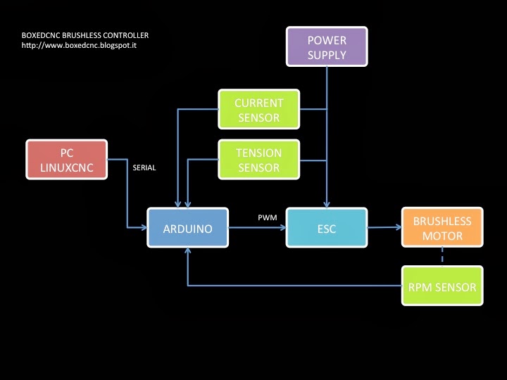
The next image shows the schematic of the brushless controller. There are four sensors in the system, but the fourth is not showed because is a temperature sensor.


The main loop in CNC mode use the GCode Spindle commands (like S5000) as target value to control with PID in a closed loop the motor RPM, trying to minimize the error between target and actual speed.


The major drawback i discovered using the affordable Turnigy ESC is the non linear response of the motor's rpm in the basic free spinning condition (without torque applied). As you can see in the next image, the RPM relation between Arduino PWM uS interval and motor RPM is something similar to a quartic function. I think this is quite common when using the writeMicroseconds function approach. In fact you can control the servo with high precision writing an interval typically between 1000uS and 2000uS. In the next graph is possible to see the real data registered regarding RPM and the Power Source output tension and current given to the ESC. Without any resistance applied to the motor's  shaft, the ESC absorbs circa 70W at the maximum speed. The power source drop voltage between zero and maximum speed is only 0.30V (from 12.87V to 12.50V).


To avoid strange PID behaviors, i needed to implement a fast transformation function. 
The rest of the post is about how i've implemented a SMA (Simple Moving Average) to smooth the RPM readings, and about the linearization of the output of the ESC.

The start is a simple moving average using integer array to take care of the fast RPM refresh process, without dedicated onboard hardware. This was software implemented using a simple array which hold a certain number of integer numbers (from 30 to 50). These values are the microseconds between two consequents falling edge (or raising, is the same) of the rpm optical sensor, collected on   interrupt pin. This happen continuously with a period in a range from 2.000 and 15.000 uS. The array index is incremented every interrupt, and is zeroed using the modulo operator in one code row.
The result is a Simple Moving Average of the continuous RPM data, which is implemented using  this code in the interrupt function:
void rpmMeter() //INTERRUPT CALLED FUNCTION
 {
   RPMIndex = (RPMIndex +1)%(RPMIndexSize-1); 
   RPMTimes[RPMIndex] = micros() - RPMTimeold;
   RPMTimeold = micros();
 };
Once 50ms i compute the sum of the array, and divide the result by number of elements in the array to obtain a smoothed RPM fresh value.

The next step is to transform the output from the horrible quartic function to a simple linear response.
This happens using another array containing the uS timing values at which corresponds the desired output. I think this is a fast method because the loop only need to lookup in a prewritten array using the index as input.


The next graph shows the test results without smoothing (real data). In the x axis there are the values of the linearized output range, in the y axis the RPM logged.


BOXED CNC: Brushless Spindle & Controller, MpIde sketch

Di seguito il link allo sketch per il Fubarino SD (MPIDE) da scaricare:

Download link: PDE SKETCH MPIDE

Richiede le seguenti librerie standard:

  • Servo.h
  • LiquidCrystal.h
  • Bounce.h
  • PID_v1.h
  • stdlib.h:

I pin utilizzati:
  • LCD RS = 10;
  • LCD E = 11;
  • LCD DB4 = 12;
  • LCD DB5 = 13;
  • LCD DB6 = 14;
  • LCD DB7 = 15;
  • VOLTAGE SENSE = A1
  • CURRENT SENSE = A3
  • RPM INTERRUPT = 4
  • SPINDLE PWM = 9

CNC Embroidery. Elettronica di controllo II

Un avanzamento sull'elettronica di controllo dell'embroidery.

L'elettronica è finalmente nella sua sede. Ho realizzato un contenitore con della plastica, in modo da formare dei compartimenti isolati e delle vie cavo dedicate.


Come previsto, l'elettronica è così composta:
  • 1 x Raspberry PI
  • 1 x Wifi key [Perfettamente funzionante con il Raspberry]
  • 1 x Arduino Uno
  • 3 x PoStep25
  • Alimentatori vari


CNC EMBROIDERY: la base in legno, parte III

Preparativi per il matrimonio.

Il tensionatore della cinghia, semplice ed efficace. Richiede tuttavia la pista libera.

Dopo qualche aggiustamento le cinghie non slittano. Ruotando a mano l'albero lo spostamento dell'asse Y non offre particolare resistenza.

La regolazione del porta cinghia forse non serviva.

Ho dovuto sostituire la boccola con una boccola compensata perché l'allineamento non è perfetto

CNC EMBROIDERY: la base in legno, parte II

Ecco qualche progresso della costruzione.
La base della macchina è realizzata come uno sportello, ovvero con telaio.
Lo stesso telaio, gli incastri, le mortase ed i tenoni sono stati fatti con la piccola MF70, spostando i profilati nella morsa. Il risultato è buono, se non fosse per il fatto che ho previsto poco gioco tra i pezzi per cui l'insieme finale non si chiude al 100%. Il prossimo verrà sicuramente meglio.

Tutti i pezzi tagliati:

Particolare della mortasa e tenone d'angolo:


Il telaio montato: 

Assemblato. Notate gli spazi nel telaio, i pezzi centrali erano indubbiamente troppo lunghi di 1 o 2 mm:


CNC EMBROIDERY: la base in legno

Qualche idea sulla base in legno; ho acquistato del noce mansonia (mi dicono che la polvere è pericolosa per la respirazione). Utilizzerò solo tre misure di profili:

  • 40x20 mm
  • 40x10 mm
  • 30x5 mm


CNC EMBROIDERY: elettronica di controllo

Una rassegna dell'elettronica di controllo.

In alto: RASPBERRY PI, ARDUINO
Al centro: 3x POSTEP-25 + interruttore ottico (per l'azzeramento del volantino)
In basso: 4 microswitch per l'homing (2 per l'asse X e 2 per l'asse Y)


Popular posts